Field Device
The edge device measures the target signals, captures local status, and prepares telemetry according to the operating schedule.
Solution Area
Remote monitoring systems must account for intermittent connectivity, limited power, unattended operation, and the need to keep data useful even when the field environment is inconsistent.
Remote monitoring is one of the strongest places for connected-device engineering to show its value. A clean dashboard is not enough if the field device cannot handle weak coverage, limited power, delayed transmission, or the reality that no one may physically visit the site for long periods.
That is why remote telemetry systems need more than transport choices. Buffering, retry logic, synchronization behavior, device-health visibility, and practical maintenance planning all shape whether the monitoring system remains trustworthy after deployment.
IoTSolutions treats remote monitoring as a system-level architecture problem rather than a single-protocol feature list. The target is reliable visibility from unattended devices, not just proof that a message can be sent once.
The exact stack depends on the operating environment, but these are the common layers and handoffs that shape this solution area.
The edge device measures the target signals, captures local status, and prepares telemetry according to the operating schedule.
Readings are retained locally so temporary network loss does not immediately translate into missing historical context.
The transport method is chosen according to coverage, power budget, infrastructure, and payload expectations.
Received telemetry is normalized and tracked so the software layer can distinguish fresh data from delayed or recovered packets.
Operators need visibility into both the monitored environment and the status of the device itself.
The node is responsible for measurement, scheduling, and enough local intelligence to handle unreliable field conditions.
Device software keeps packets recoverable and retries predictable instead of assuming a perfect uplink path.
The communications layer may be GSM/LTE, LoRa, Wi-Fi, or another fit-for-environment choice.
Dashboards, alerts, and status views convert remote telemetry into operational visibility.
Coverage, latency, and data cost change how frequently the system can send and how much it should defer locally.
Remote systems often depend on power-aware scheduling, selective transmission, and realistic assumptions about battery or solar support.
Device-side storage and recovery logic can matter more than the protocol name when connectivity becomes unstable.
Battery status, signal condition, restart visibility, and last-contact indicators help reduce blind maintenance work.
The system should help diagnose whether failures are environmental, electrical, or network-related.
Remote sensor stations
Equipment telemetry from unattended sites
Battery-powered field monitoring
Device-health and status dashboards
Offline-first telemetry synchronization
Core Service
Connected system design spanning devices, firmware, communications, data flow, and operator-facing interfaces.
Firmware & Device Logic
Firmware-focused development for microcontroller-based systems, sensor interfaces, device logic, and hardware integration.
Proof of Concept
Prototype-oriented engineering for evaluating sensors, modules, power approaches, and early connected-system ideas.
Communications Strategy
Connectivity planning and remote telemetry system design shaped by range, power, reliability, infrastructure, and field conditions.
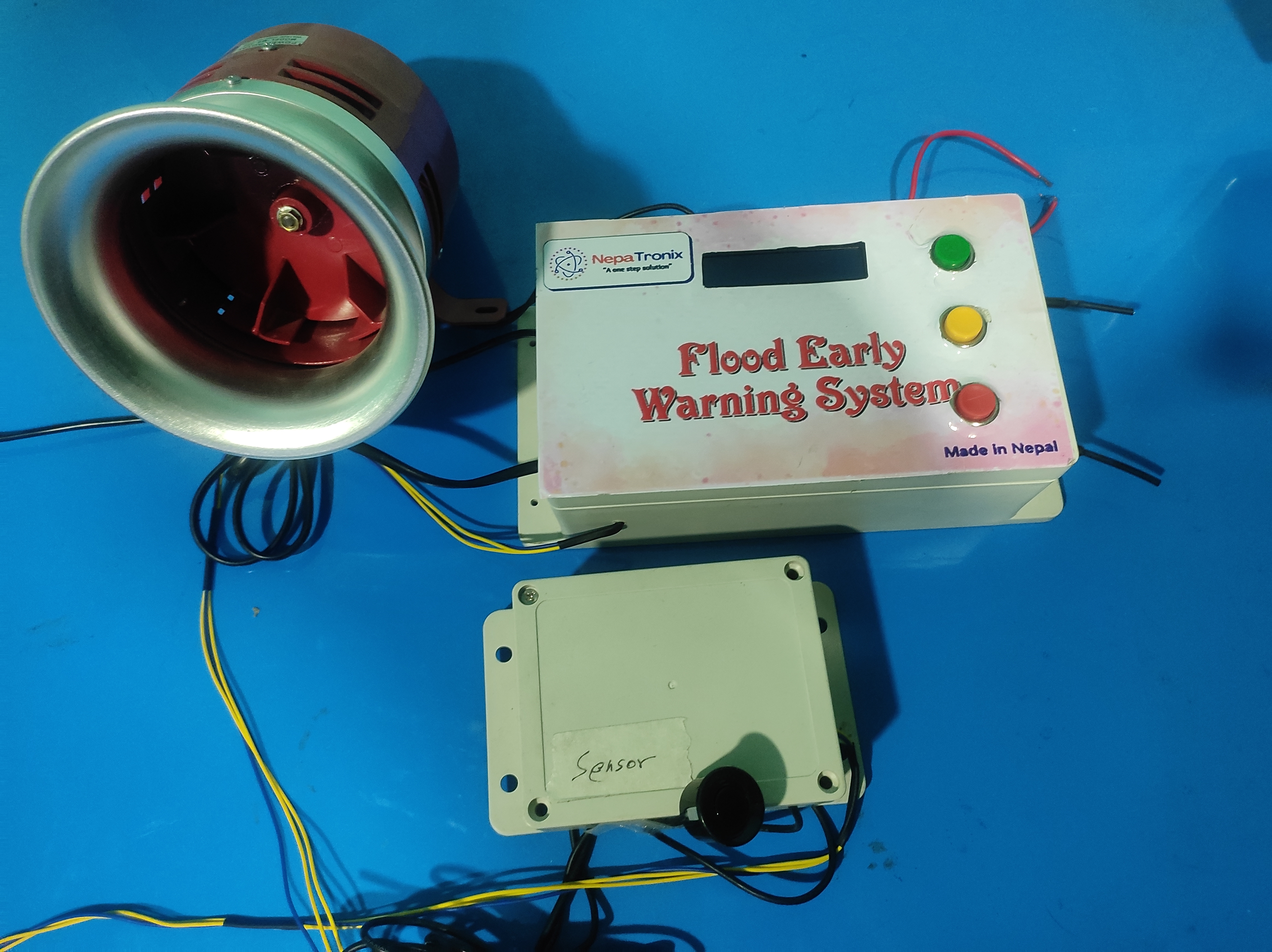
A real-time flood early warning system using ultrasonic water-level sensing, LoRa communication, multiple connected nodes, and a 120 dB siren for automatic and manual alerts.
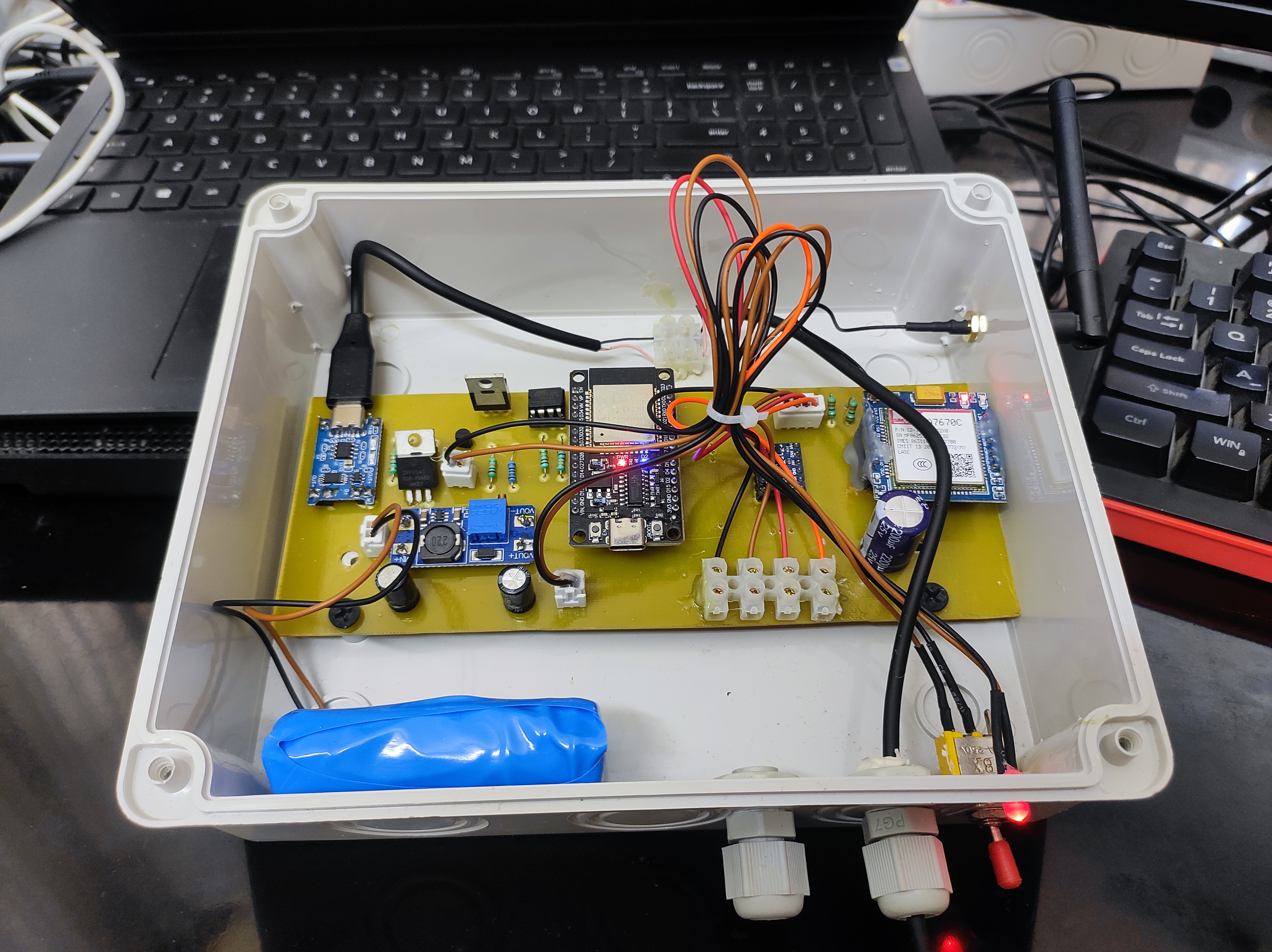
A compact ESP32-based microclimate monitoring device using an SHT45 sensor, GSM communication, OTA firmware updates, and 18650 Li-ion battery backup.
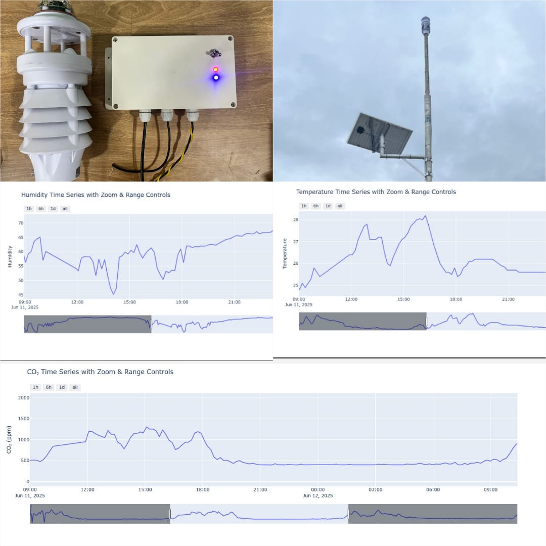
A solar-powered ESP32 weather station that monitors temperature, humidity, CO₂, light intensity, wind, PM2.5, and PM10 using RS485-connected sensors and GSM-based remote communication.
Next Step
We can discuss the sensing strategy, embedded logic, connectivity approach, and software visibility that make the solution practical in the field.